Chapter 2.4
Chapter 2.6
2.5 Interpret basic operations of Rapid PVST+ Spanning Tree Protocol
2.5.a Root port, root bridge (primary/secondary), and other port names
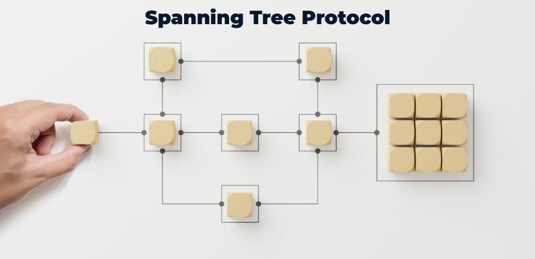
Rapid PVST+ (Per-VLAN Spanning Tree Plus) is an extension of the Spanning Tree Protocol (STP) that provides a separate spanning tree for each VLAN in a network. The basic operations of Rapid PVST+ include determining the root bridge, electing root ports, and assigning different port names.
Root Bridge:
The root bridge is a switch in a spanning tree network that serves as the central point of reference. It is responsible for determining the topology of the network by advertising the lowest Bridge ID. Rapid PVST+ elects a single root bridge for each VLAN based on the Bridge ID, which consists of a priority value and a MAC address. The switch with the lowest Bridge ID becomes the root bridge.
Root Port:
The root port is the switch port that provides the best path to reach the root bridge. Each non-root switch in the network determines its root port by comparing the costs of the received Bridge Protocol Data Units (BPDUs) from neighboring switches. The port with the lowest cost becomes the root port.
Primary and Secondary Root Bridge:
In Rapid PVST+, each VLAN can have a primary and a secondary root bridge. The primary root bridge is the switch with the lowest Bridge ID for a specific VLAN. The secondary root bridge is the switch with the second-lowest Bridge ID. Having a secondary root bridge helps in maintaining redundancy and provides an alternate path in case the primary root bridge fails.
Other Port Names:
Besides the root port, there are other port names used in Rapid PVST+:
✓ Designated Port: This is the switch port that is selected on each LAN segment to forward traffic towards the root bridge. Each LAN segment has only one designated port.
✓ Non-Designated Port: Any switch port that is not designated is considered a non-designated port. Non-designated ports are put into a blocking state to prevent loops in the network.
✓ Alternate Port: An alternate port is a backup port that provides an alternative path to reach the root bridge. Alternate ports are kept in a blocked state but are ready to transition to the forwarding state if the current root port fails.
✓ Backup Port: A backup port is similar to an alternate port but serves as a backup for a specific designated port. It is in a blocking state and becomes active only if the designated port fails.
2.5.b Port states (forwarding/blocking)
Port States: Rapid PVST+ uses several port states to manage the spanning tree topology. These states are:
✓ Blocking: A port in the blocking state does not forward any data frames but listens to BPDUs to gather information about the spanning tree topology. Blocking state prevents loops by stopping any traffic from being transmitted or received through that port.
✓ Forwarding: A port in the forwarding state actively forwards data frames. It is the desired state for a switch port to be in, allowing traffic to pass through.
✓ Disabled: A disabled port is administratively shut down and does not participate in the spanning tree operations. It is effectively removed from the spanning tree topology.
✓ Learning: The learning state is a transitional state during which a port listens to BPDUs and starts populating its MAC address table by learning the source MAC addresses of incoming frames.
✓ Discarding: The discarding state is also a transitional state during which a port listens to BPDUs and discards any incoming or outgoing frames. It is a part of the spanning tree convergence process.
2.5.c PortFast:
PortFast is a Cisco-specific feature that allows for the rapid transition of a port from the blocking state to the forwarding state. By enabling PortFast on a switch port, the port is immediately placed into the forwarding state without going through the listening and learning states. PortFast is typically used for end-user ports, such as those connected to computers or IP phones, where there is no risk of creating a switching loop. It helps devices connected to the port to become operational quickly without waiting for the spanning tree convergence process.
Topology Diagram
Tasks
● Note: The enable passwords for all devices is "CISCO".
● Configure hardcore 802.1q trunk on links between SW02 and SW04, and SW04 and SW03.
● Delete layer 3 portchannel3 configured between SW02 and SW03. Instead configure 802.1q on link between these switches.
● Access switches SW02, SW03, and SW04 and perform the configuration for Rapid Spanning-Tree.
● Set SW02 as the STP Root Bridge for VLAN-3, utilizing a command that automatically assigns the appropriate STP Bridge Priority value.
● SW04 as the STP Root Bridge for VLAN-4, manually setting the Bridge Priority value to 4096.
● Execute the command "show spanning-tree root*" on SW02 and observe which switch assumes the role of Root Bridge for VLAN-1. Do not employ the "show spanning-tree vlan 1" command for this step. Based on the Root Bridge for VLAN-1 and the fact that each link is an Ethernet link, answer the following questions:
✓ Identify the Root Bridge for VLAN-1.
✓ Can you predict at least one port in the Discarding state solely by examining the output of "show spanning-tree root" on SW02?
● Apply the necessary Spanning-Tree configuration commands on your switches to achieve the following:
✓ SW04 designates interface E1/1 as its STP Root Port for VLAN-3.
✓ To confirm that your configuration changes have taken effect as intended, review the output of "show spanning-tree vlan 3" on SW04.
● On SW02, SW03, and SW04, configure any interface that directly connects to a router or PC in a manner that ensures the interface transitions immediately to the "Forwarding" state upon activation.
Configuration and Verifications
Configure rapid spanning tree on SW02, SW03 and SW04 using command "spanning-tree mode rapid-pvst". SW02 should be the root bridge for VLAN 3 using "spanning-tree vlan 3 root primary" command. SW04 should be the root bridge for VLAN 3 using "spanning-tree vlan 4 priority 4096" command.
Note: As per task, manually configure 802.1q on links between SW02, SW03 and SW04. Delete layer3 portchannel between SW02 and SW03. Configure 802.1q trunk and allow vlan 1-5 between these links.
SW02:
!
configure terminal
!
no interface po3
!
default interface E0/0
!
interface E0/0
switchport
switchport trunk encapsulation dot1q
switchport mode trunk
switchport trunk allowed vlan 1-5
!
interface range E1/0, E0/3
switchport trunk encapsulation dot1q
switchport mode trunk
!
spanning-tree mode rapid-pvst
spanning-tree vlan 3 root primary
!
end
!
write
!
SW03:
!
configure terminal
!
no interface po3
!
default interface E0/1
!
interface E0/1
switchport
switchport trunk encapsulation dot1q
switchport mode trunk
switchport trunk allowed vlan 1-5
!
interface range E1/1, E0/2
switchport trunk encapsulation dot1q
switchport mode trunk
!
spanning-tree mode rapid-pvst
!
end
!
write
!
SW04:
!
configure terminal
!
interface range E1/0-1, E0/0, E0/2
switchport trunk encapsulation dot1q
switchport mode trunk
!
spanning-tree mode rapid-pvst
spanning-tree vlan 4 priority 4096
!
end
!
write
!
Now verify that SW02 is the root bridge for VLAN 3 and SW04 is the root bridge for VLAN 4
SW02:

SW04:

On SW02, the output of "show spanning-tree root" command determines that root bridge for VLAN 1 is SW02 itself because cost is 0 to reach to the root bridge. So, all of SW02 ports for VLAN 2 are root ports and SW03 and SW04 can send traffic directly to SW02. Therefore, either SW03 or SW04's po1 will be in blocking state.
SW02:

Currently SW04 has Po2 as root port because it has the lower cost to reach to the root bridge (SW02) for VLAN 3.
SW04:

If you increase Po2 cost to a high value (higher that cumulative cost from SW04 to SW03 to SW02) the Po1 will become root port on SW04 for VLAN-3.
!
configure terminal
!
interface Po2
spanning-tree vlan 3 cost 1000
!
end
!
write
!
Verify the root port again on SW04. This time root port has changed to Po1 instead of Po2.

Use "spanning-tree portfast" command on switches (SW02, SW03 and SW04) interfaces directly connected end hosts (routers, PC etc.) to ensures the interface transitions immediately to the "Forwarding" state upon activation.
SW02:

SW03:

SW04:

Don't Miss to Checkout our Next Articles
Exploring CDP Protocol and LLDP
Understanding IP Addressing and Subnetting
Other Popular & Useful Articles
Steps for Cisco Port Channel Configuration
Configuring Trunk Ports and Native VLANs on Cisco
Comments (0)
Categories
Popular posts


Cisco Nexus Port Channel: Configuring ...
6 May 2024
Configure Rapid PVST on Cisco Nexus
26 Apr 2024
Palo Alto Exam Cost: PCNSA, PCNSE & More
27 Apr 2024
Cisco ACI VPC Configuration Task Steps
28 Apr 2024Recent posts

CCNA Exam Fees and Expenses Breakdown
16 May 2024
CCNA vs CCNP Certification: Differences
16 May 2024
What is CCNA: Exploring Its Significance
16 May 2024
Step by Step cisco WLC configuration
15 May 2024


