Cisco is a critical player in providing IT infrastructure solutions to thousands of organizations. As a part of learning and development of its network hardware devices and other product, Cisco offers certification programs starting with CCNA for beginners that comes under cisco enterprise technologies offering.
It covers the core networking concepts, students learn and build a strong foundation for grasping advance technologies. Lets now understand the networking devices.
1.1 Explain the Role and Function of Network Hardware Devices
This is the first topic of Cisco CCNA course syllabus. In brief, the following are the list of devices used in networking, there may be more peripherals and components.
1. Hub
2. Switch
3. Bridge
4. Router
5. Firewall
6. Intrusion Prevention System (IPS)
7. Wireless Access Point (WAP or AP)
8. Wireless LAN Controller (WLC)
9. Cisco Digital Network Architecture (DNA)
10. Advanced Programmable Interrupt Controller (APIC)
11. Cisco Nexus Switches
12. Cisco IP Phones
13. Cisco Storage Devices (UCS)
In this blog we will be covering the main network component's role and function which are a part of CCNA and will understand them based on real scenarios and device configurations.
This will help you to better understand the network hardware devices and how they work in production environment. Additionally if you want to learn concepts with hands-on practice via instructor led live training on CCNA.
1.1a Routers
Routers are the core component of the networking devices which you see in the organization's data centers or branch offices or small home office network.
These routers operate on network layer which is Layer 3 of the OSI model.
The primary role of a router is to connect two or more different networks which facilitate the exchange of data packets between the networks.
These routers can take decisions based on the destination IP addresses present in the received packets. It determines the most appropriate outgoing interface based on existing routing table for forwarding those packets to the next router in the network.
These routing table are formed with the help of static routes or routing protocols like OSPF, EIGRP or BGP etc.
We will understand the functionality of router based on below scenario. Understanding of IP addressing is essential before proceeding as these are the critical elements of network building blocks..
Scenario: In a corporate network or a small home office network, typically router's interface connects to internal network called the local area network (LAN) and other interface connects to the internet or WAN or Public network.
When an internal device which is a part of LAN initiates a date packets, this router first receives these data packets and looks up the destination IP address present inside the data packets.
Based on the routing table (As depicted in the below diagram, here routing table is built from configured default route) it then forwards them to the appropriate interface to send on the internet.
The return data packets are received by the router and forwarded to the same devices which generated that data packets.

Here is the Cisco router configuration:
!
interface GigabitEthernet0/0
ip address 192.168.1.1 255.255.255.0
!
interface GigabitEthernet0/1
ip address 10.0.0.1 255.255.255.0
!
ip route 0.0.0.0 0.0.0.0 10.0.0.254
!
In this example, the router has two interfaces. GigabitEthernet0/0 is connected to the LAN with the IP address 192.168.1.1, and GigabitEthernet0/1 is connected to another network called Internet with the IP address 10.0.0.1.
The "ip route" command sets the default gateway for the router, specifying that any traffic with unknown destinations should be forwarded to the IP address 10.0.0.254.
1.1.b Layer 2 and Layer 3 switches
The switches which are operated at Layer 2 and Layer 3 of the OSI model have different functionalities. Here are some of the Cisco switches model.

Layer 2 switches operate at the data link layer (Layer 2) and primarily focus on forwarding Ethernet frames based on MAC addresses.
They build and maintain MAC address tables to learn which devices are connected to which switch ports. Layer 2 switches are responsible for local network segmentation, improving network performance, and reducing collision domains.
Lets take a scenario to understand the functional role of the another network hardware devices i.e. switch
Scenario: In an office network, a Layer 2 switch connects multiple computers and devices within a LAN.
When a device sends data to another device within the same LAN, the Layer 2 switch examines the MAC addresses in the Ethernet frames and forwards them to the correct destination port.
Devices in same VLANs can communicate with each other while devices in different VLANs require their respective VLANs gateways IP addresses configured either on Layer 3 switch or a router.
Here is the configuration of a Layer 2 switch.
!
interface FastEthernet0/1
switchport mode access
switchport access vlan 10
!
interface FastEthernet0/2
switchport mode access
switchport access vlan 20
!
vlan 10
name Sales
!
vlan 20
name Marketing
!
In this example, the switch has two ports configured as access ports. Port FastEthernet0/1 is assigned to VLAN 10 (Sales), and port FastEthernet0/2 is assigned to VLAN 20 (Marketing). The "vlan" command is used to create the VLANs and assign names to them.
Layer 3 switches, also known as multilayer switches, combine the features of Layer 2 switches with routing capabilities found in routers. They can perform routing functions at wire speed and facilitate inter-VLAN communication by routing traffic between different VLANs.
A this point you may be wondering if we already have routers which work at layer 3 then what these layer 3 switches do and what are the differences between router and switch.
Scenario: Sometimes in a network, it is required to have multiple VLANs for various reasons. In that case a Layer 3 switch can be configured as a default gateway for these VLANs. These VLANs can then route traffic between each other on the switch. It examines the IP addresses in packets and forwards them based on the routing table entries.
Here is the configuration of a Layer 2 switch.
!
interface GigabitEthernet0/1
switchport mode trunk
!
interface Vlan10
ip address 192.168.10.1 255.255.255.0
!
interface Vlan20
ip address 192.168.20.1 255.255.255.0
!
ip routing
!
In this example, the switch has a trunk port (GigabitEthernet0/1) to carry VLAN traffic. Two VLAN interfaces (Vlan10 and Vlan20) are configured with IP addresses. The "ip routing" command enables routing functionality on the Layer 3 switch. These IP addresses are the gateways on the devices in their respective VLANs,
The above mentioned switches are Cisco catalyst switches and mostly you can use them as access switches in live production environment where users directly connected. You can learn about these switch with some basic training and hands-on exercises.
There are heavy duty data center cisco nexus switches, you can use these switches where they can handle high volume of network traffic and scalability is not a challenge. These nexus switches are also come up with fully functional automation through software defined network called cisco aci switches used in plug and play environment.
Once you are comfortable in cisco access switches you can go ahead and start learning cisco nexus and aci switches either through self paced videos or via instructor led live training. Learning these skills will keep you on top and will give you much more opportunities in the near future.
1.1.c Next-generation firewalls and IPS
Next-generation firewalls (NGFWs) and Intrusion Prevention Systems (IPS) are security of network hardware devices or software designed to protect vulnerable networks from malicious activities, unauthorized access, and threats.
Cisco firepower is a cutting edge security solution for protecting networks from advance threads and attacks. It is relative new device so there are not many training available on internet for free.
However organizations are deploying at large scale. Live training on cisco firepower will equip professional candidates to manage, operate and implement such security solutions. Even professionals who are already working on such devices, they require to test some features on proof of concept firepower virtual labs before deploying on production equipment's.
Here just focus on basic hardware and initial configuration of these devices, but you can certainly go ahead and learn more about it either from Cisco or UniNets live training.
The picture below is the Cisco Firepower 1000 series appliances, this is considered as NGFW.

NGFWs combine traditional firewall features (such as stateful packet inspection) with advanced capabilities such as application-layer filtering, user identity awareness, and threat intelligence.
They inspect network traffic at multiple layers, including application, transport, and network layers, to enforce security policies and prevent unauthorized access. Below are couple of scenarios where IPS or NGFW is used.
Scenario 1: In an enterprise network, an NGFW is deployed at the network perimeter to inspect incoming and outgoing traffic. It can block malicious websites, detect and prevent intrusions, and provide granular control over network applications and user access.
IPS systems monitor network traffic for suspicious patterns or known attack signatures. They analyze packets in real-time to identify and block malicious activities.
Scenario 2: In a data center environment, an IPS is deployed to monitor traffic between servers. It can detect and prevent attacks like DDoS, SQL injection, and buffer overflow by inspecting the content of network packets.
Here's a simplified example of configuring access control policies on a Cisco NGFW (ASA):
!
access-list WEB_TRAFFIC permit tcp any any eq 80
access-list WEB_TRAFFIC permit tcp any any eq 443
access-list BLOCK_TRAFFIC deny ip any any
!
class-map WEB_CLASS
match access-list WEB_TRAFFIC
!
policy-map BLOCK_WEB_POLICY
class WEB_CLASS
inspect http
inspect https
!
service-policy BLOCK_WEB_POLICY interface outside
access-group BLOCK_TRAFFIC in interface outside
!
In this example, an access control list (ACL) is created to permit web traffic (TCP ports 80 and 443). Another ACL denies all IP traffic.
A class map is defined to match the web traffic ACL, and a policy map is created to inspect HTTP and HTTPS traffic. The policy is then applied to the outside interface, and the access-group command applies the blocking ACL to the outside interface.
1.1.d Access points
Access points (APs) are the wireless network hardware devices which are used to send Wi-Fi singles for providing the wireless connectivity to the wireless devices in a specified area. They act as a bridge between wireless devices and the wired network infrastructure.
The picture below is the Cisco Wireless Aironet 3600 series access points.

Scenario: In a Wi-Fi network, access points are strategically placed throughout an office building to ensure reliable wireless coverage. All the wireless components of computer networks supported devices such as laptop, phones etc. tries to connect to wireless network, they first get them self attached with the nearest available access point. The access point handles the transmission of data packets between wireless devices and the network.
Here's a simplified example of configuring a Cisco Aironet access point:
!
interface Dot11Radio0
ssid ExampleNetwork
!
interface GigabitEthernet0
switchport mode trunk
!
interface BVI1
ip address 192.168.1.1 255.255.255.0
!
In this example, the access point has a wireless interface (Dot11Radio0) configured with the SSID "ExampleNetwork." The GigabitEthernet0 interface is configured as a trunk port to carry multiple VLANs. The BVI1 interface is configured with an IP address for management purposes.
1.1.e Controllers (Cisco DNA Center and WLC)
Controllers are network management devices that provide centralized management and control for various network components in computer networks, such as access points and switches.
Cisco DNA Center is a software-based network controller that enables centralized management, automation, and assurance for enterprise networks. It provides a single dashboard for managing network devices, implementing policies, and monitoring network health.
The picture below is the dashboard of DNAC.

Scenario: The computer network hardware devices such as router, switches, firewalls, access points etc. are being manages and monitored by DNA Center.
It is preferably used in a large enterprise environment where it is difficult to manage them manually.
With the help of DNA, network engineers can perform various functions such as upgrading of IOS on devices from a centralized location and can also troubleshoot network issues without logging into each device.
As Cisco DNA Center is a software-based controller, there is no specific configuration example. However, typical tasks performed through Cisco DNA Center include:
● Adding network devices (routers, switches, access points) to the inventory.
● Creating network profiles for devices and applying standardized configurations.
● Defining policies for network access, security, and quality of service.
● Monitoring network health, performance, and security.
● Automating network operations and deploying software updates.
Cisco Wireless LAN Controller is a specialized controller designed for managing wireless networks. You can also learn further about it from a video course.
It centralizes the configuration, security, and management of access points. The picture below is the Cisco Wireless LAN Controller 5500 series.

Scenario: In a wireless network deployment, its easy to configure and setup Cisco WLC which is used to manage multiple access points. It handles tasks such as AP discovery, client authentication, and radio resource management to ensure efficient and secure wireless connectivity. The WLC training videos explain the full process of discovery and authentication with hands-on exercises starting with initial setup.
1.1.f Endpoints
Endpoints are the device connected to the user ports of the network switches. These devices are the one who send and receives the data for the end users such devices include laptops, desktops, cameras, phones etc.
Scenario: In a typical office network, endpoints can include employee workstations, laptops, and mobile devices. Applications run on these devices to perform tasks like sending emails, sharing files, browsing internet etc.
1.1.g Servers
Servers are the high-end computer network hardware devices that provide resources such as CPU, RAM, Hard disk for storage etc. for executing various services on a network. They are designed to handle specific tasks and deliver resources efficiently.
Basically there are 2 most popular i.e. open source Linux servers and proprietary Windows servers. In linux there are several flavors like ubuntu, redhat, kali, suse etc. with their release versions and similarly in windows we have windows 2010, 2012, 2016 etc.
Scenario: In an enterprise network, servers play a crucial role in providing various services. These services include storage, compute, web hosting, email service, database etc.
1.1.h PoE
Power over Ethernet (PoE) is a technology which provides power and data to the end network components in computer networks over the same ethernet cable.
With PoE, power sourcing equipment (such as PoE switches) can deliver electrical power to PoE-enabled devices without the need for separate power cables.
The picture below is the Cisco Catalyst c2960x 48 port PoE switch, a normal twisted pair ethernet cable is required to connect from switch ports to the end devices such as access point (access point does not require any other external power) to withdraw power.

Scenario: In a network deployment, PoE is commonly used to power up the components of computer networks such as IP phones, wireless access points, and security cameras etc.
This eliminates the need for additional power outlets near these devices and simplifies cabling.
Here's an example configuration for a Cisco PoE switch:
!
interface GigabitEthernet0/1
power inline auto
!
interface GigabitEthernet0/2
power inline static
power inline consumption 15000
!
In this example, GigabitEthernet0/1 is configured to automatically detect and provide power to a connected PoE device. GigabitEthernet0/2 is configured to deliver a static amount of power (15,000 milliwatts) to the connected device.
Don't Miss to Checkout Our Next Articles:
Cisco Hardware Networking Devices
What are the difference between Routers and Switches
Other Popular & Useful Articles
Comments (0)

Categories
Popular posts

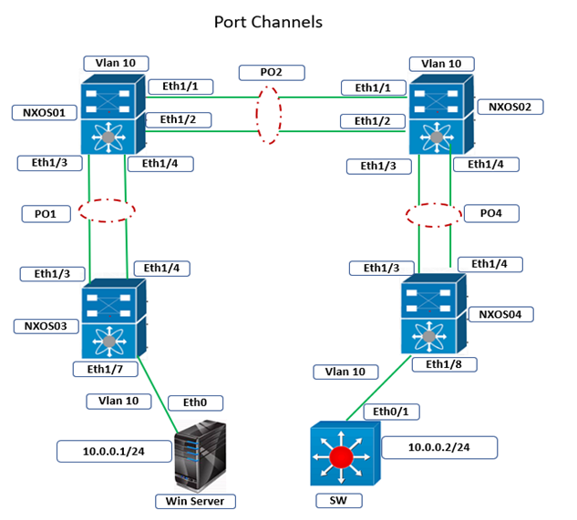
Cisco Nexus Port Channel: Configuring ...
26 Apr 2024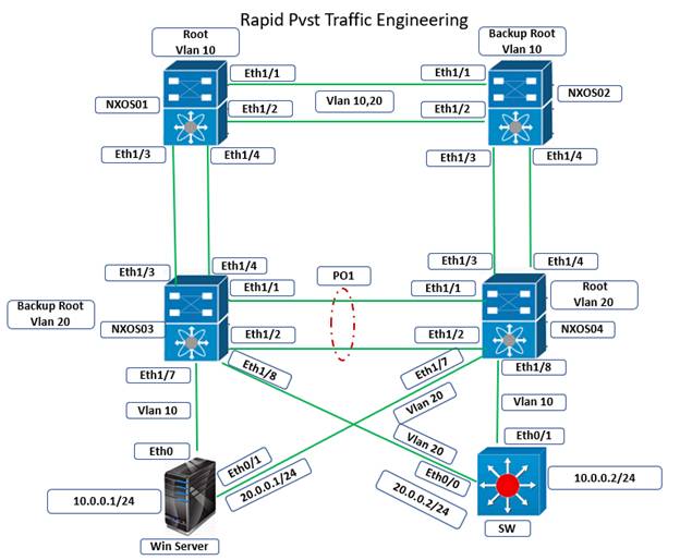
Configure Rapid PVST on Cisco Nexus
26 Apr 2024
Palo Alto Exam Cost: PCNSA, PCNSE & More
27 Apr 2024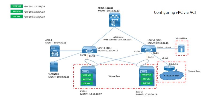
Cisco ACI VPC Configuration Task Steps
28 Apr 2024Recent posts
Types of Network Topology: Explained
3 May 2024
Difference between TCP and UDP: Compared
3 May 2024
Difference between Router-Switch: An ...
3 May 2024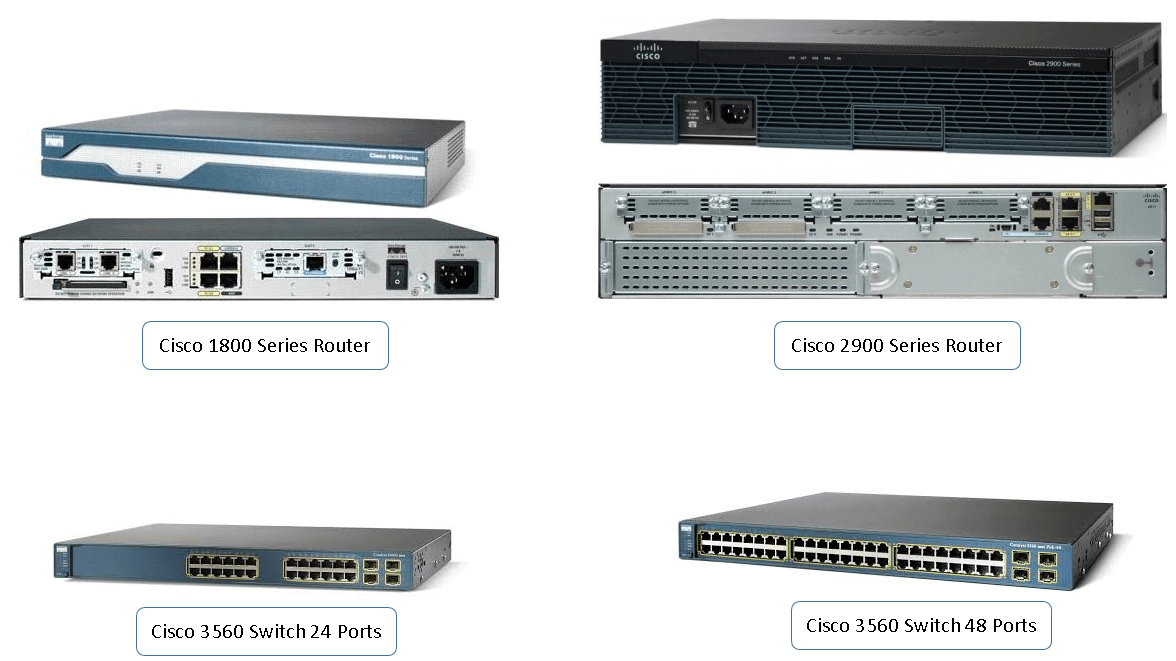
Cisco Hardware Devices
3 May 2024