Few years back I was given an opportunity of replacing a N5K switch from vPC. Some of the physical connectivity was already there, here is what I performed from the start. Before this change I also referred Cisco documents but in documents there are several steps which were wrong. So, I thought to write my steps what I saw and performed during this replacement process of one of the N5k switch and then bring the vPC up for the all the FEX connected to these pair of switches.
The steps followed in order to bring the switch in production.
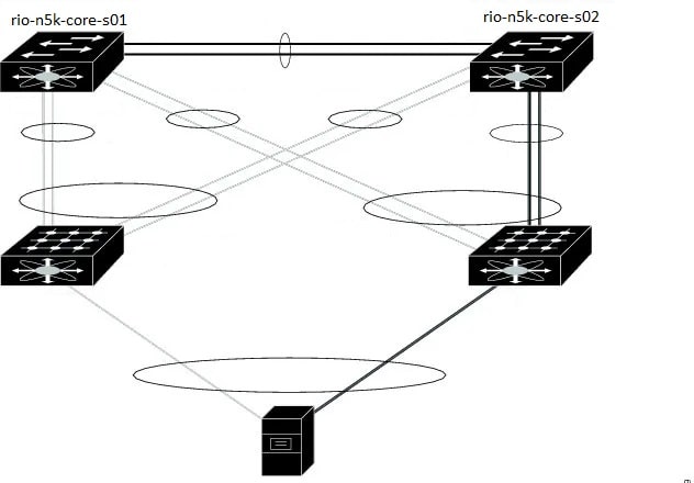
1. Replacement switch “rio-n5k-core-s01” is already running the same NX-OS image as its peer and already has configuration. Some interfaces were shut down, including peer-link and management interface on core-01 was shut down on connected router. Everything is connected on replacement switch.
2. Existing configuration had ‘auto-recovery’ and core-01 had ‘role priority 1’ so we removed auto-recovery from both switches, and changed role priority to 40000 on core-01 to avoid any traffic impact to rio-n5k-core-s02.
3. Pre-Provisioning configuration was added to core-01, when we brought up the peer keepalive interface on mgmt0, and vPC peer-link, we noticed hosts were down. Logs observed on core-02 saying VLANs are being suspended.
rio-n5k-core-s02# show logging last 20
2015 Jun 10 02:06:01.895 rio-n5k-core-s02 %ETHPORT-3-IF_ERROR_VLANS_SUSPENDED: VLANs 400 on Interface Ethernet199/1/9 are being suspended. (Reason: Vlan is not allowed on Peer-link)
2015 Jun 10 02:06:01.897 rio-n5k-core-s02 %ETHPORT-3-IF_ERROR_VLANS_SUSPENDED: VLANs 82 on Interface Ethernet198/1/9 are being suspended. (Reason: Vlan is not allowed on Peer-link)
2015 Jun 10 02:06:01.899 rio-n5k-core-s02 %ETHPORT-3-IF_ERROR_VLANS_SUSPENDED: VLANs 483 on Interface Ethernet197/1/48 are being suspended. (Reason: Vlan is not allowed on Peer-link)
We checked core-01 and found it is missing VLAN configuration, the only allowed VLAN on port-channel 100 (peer-link) was 1 and 600. (Please note, interface VLAN 600 is the IP address / connection we were using to get into Core-01 while the mgmt0 interface was shut down.) Added all the VLANs back and host interfaces were still showing DOWN (INACTIVE), this is because we omitted to configure the host interfaces on core-01. The old configuration on core-01 was put back including the host interface configurations, and hosts started to recover.
Some port-channels 403 to 410 didn’t come up on Core-01, host interfaces were missing the ‘channel-group’ statements, therefore showing DOWN (inactive) and no operational members shown on port-channel interface. To resolve this, had to use the ‘force’ option to add the configuration back in. That is:
interface Ethernet198/1/1
channel-group 403 force mode active
Core-01 was VTP server, and core-02 is VTP client, and the VTP domain name was already configured on both switches. A switch with highest Configuration Revision should distribute the VLAN configuration. However, VTP password wasn’t configured on core-01 so didn’t sync the VLANs. In hindsight, we were fortunate because had the Configuration Revision on Core-01 was higher, then it would’ve wiped out existing Core-02’s VLAN configuration!
To explain why servers were down when one side of the host interfaces (HIF) were missing configuration. This is because from the servers’ perspective, it will select any path that is UP. Physically, the servers are connected to both FEXs, and the interfaces are UP, so if the server selected the path to the switch that had missing configuration, then the traffic will be black holed.
There were some issues faced in this procedure where traffic was black holed, to avoid such problems make sure point 3 must be considered.
To avoid future problems with replacement, this is what should be checked or considered.
1. Make sure that NX-OS on both the switches are exactly the same if not please upgrade/downgrade the NX-OS of the replacement switch same as the existing switch.
2. Shut down all the links including keepalive and peer-link port-channel. If this switch needs remote access, an uplink must be configured for the same.
3. Shutting down mgmt0 and port-channel peer-link
4. Need to verify VTP / VLAN configuration – ‘show vtp status’, ‘show vlan summary’, ‘show vlan brief’. Make sure it has to be in sync with the other switch.
Pre-provision FEX by doing the below:
switch# configure terminal
switch(config)# slot 110
switch(config-slot)# provision model N2K-C2232P
switch(config-slot)# exit
switch(config)# interface Ethernet110/1/1
switch(config)#
switch(config)# interface Ethernet110/1/2
switch(config)#
If vPC auto-recovery is enabled, disable it on both vPC peers using the “no auto-recovery” command under the vPC domain. This is to ensure that there is no vPC role change when the replacement switch is brought up.
Ensure the vPC role priority of the currently running switch is better than on the replacement switch. The switch with lower priority will be elected as the vPC primary switch; default value for role priority is 32667.
Once configurations on both switches are identical, then you can connect peer keepalive link first. Once up, then bring up peer-link.
Verify the vPC, “show vPC” on both switch, also verify fex are online “show fex”
Verify if all services are running as expected.
Comments (0)

Categories
Popular posts

Cisco Nexus Port Channel: Configuring ...
26 Apr 2024
Configure Rapid PVST on Cisco Nexus
26 Apr 2024
Palo Alto Exam Cost: PCNSA, PCNSE & More
26 Apr 2024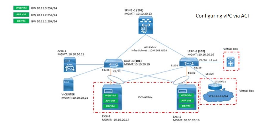
Cisco ACI VPC Configuration Task Steps
6 Jan 2024Recent posts
Network Hardware Devices: Explained
26 Apr 2024
Configure Rapid PVST on Cisco Nexus
26 Apr 2024
Palo Alto Exam Cost: PCNSA, PCNSE & More
26 Apr 2024
Cisco Nexus Port Channel: Configuring ...
26 Apr 2024