In the enterprises IT infrastructure, there are several switches used for LAN from access layer to core layer switches and mostly these are cisco data center. The core layer includes cisco nexus switches for handling heavy traffic forwarding.
Cisco nexus switches have NX-OS operating system and which runs Rapid PVST (Per-VLAN Spanning-Tree Protocol) by default.
This means that for each created VLAN, there is a separate instance of STP (spanning tree protocol) running on each nexus switches. It runs 802.1w RSTP algorithm with each instance of stp.
The default behavior of spanning tree on Cisco NX-OS is essentially identical to that of Catalyst IOS.
Before getting deep dive further into understanding Cisco nexus configure rapid pvst, I like to share that I have picked these lab tasks from a cisco nexus lab manual practice guide and used remote labs for its implementation.
In case if you like to practice this lab either build a similar lab topology on your own lab or lab rental for cisco nexus switching like I mentioned above.
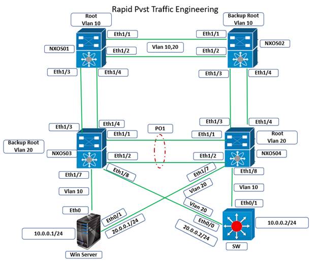
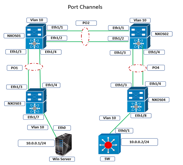
Tasks: Cisco Nexus - Configure Rapid PVST
● Erase the previous configuration on switches NXOS01, NXOS02, NXOS03 and NXOS04 using command “write erase” and reload both switches, assign hostname the same hostname to both switches. Use provisioning documents if required
● Configure all links connecting NXOS01, NXOS02, NXOS03, and NXOS04 as 802.1Q trunk ports.
● Configure the links connecting NXOS03 and NXOS04 as a port channel 1.
● Create VLANs 10 and 20 on all switches, and assign them as follows:
a) Win Server’slink to NXOS03 should be in VLAN 10 and use the IP address 10.0.0.1/24.
b) Win Server’slink to NXOS04 should be in VLAN 20 and use the IP address 20.0.0.1/24.
c) SW’s link to NXOS03 should be in VLAN 20 and use the IP address 20.0.0.2/24.
d) SW’s link to NXOS04 should be in VLAN 10 and use the IP address 10.0.0.2/24.
● Configure Spanning-Tree Protocol between the switches as follows:
a) All switches should use 32 bits for spanning-tree port path costs.
b) NXOS01 should be the STP Root Bridge for VLAN 10, with NXOS02 being the backup Root Bridge.
c) NXOS04 should be the STP Root Bridge for VLAN 20, with NXOS03 being the backup Root Bridge.
d) Win Server’s VLAN 10 traffic to SW should follow the path of NXOS03 ->NXOS02 ->NXOS01 ->NXOS04 ->SW.
e) SW’s VLAN 20 traffic to Win Server should follow the path of NXOS03 ->NXOS01 ->NXOS02 ->NXOS04 -> Server 1.
● Keep saving your configuration using command “copy run start”
Rapid PVST Cisco Configuration
NXOS03:
! vlan 10,20 ! spanning-tree pathcost method long ! spanning-tree vlan 20 priority 8192 ! interface Ethernet1/1-2 switchport switchport mode trunk channel-group 1 no shutdown ! interface port-channel1 switchport mode trunk spanning-tree vlan 10,20 cost 99999 ! interface Ethernet1/3-4 switchport switchport mode trunk spanning-tree vlan 10 cost 99999 no shutdown ! interface Ethernet1/5-6 switchport switchport mode trunk spanning-tree vlan 20 cost 99999 no shutdown ! interface Ethernet1/7 switchport switchport access vlan 10 no shutdown ! interface Ethernet1/8 switchport switchport access vlan 20 no shutdown ! |
NXOS04:
! vlan 10,20 ! spanning-tree pathcost method long ! spanning-tree vlan 20 priority 4096 ! interface Ethernet1/1-2 switchport switchport mode trunk channel-group 1 no shutdown ! interface port-channel1 switchport mode trunk ! interface Ethernet1/3-6 switchport switchport mode trunk no shutdown ! interface Ethernet1/7 switchport switchport access vlan 20 no shutdown ! interface Ethernet1/8 switchport switchport access vlan 10 no shutdown |
NXOS01:
! vlan 10,20 ! spanning-tree pathcost method long ! spanning-tree vlan 10 priority 4096 ! interface Ethernet1/1-2 switchport switchport mode trunk no shutdown ! interface Ethernet1/3-4 switchport switchport mode trunk spanning-tree vlan 10 cost 99999 no shutdown ! interface Ethernet1/5-6 switchport switchport mode trunk spanning-tree vlan 20 cost 99999 no shutdown ! |
NXOS02:
! vlan 10,20 ! spanning-tree pathcost method long ! spanning-tree vlan 10 priority 8192 ! interface Ethernet1/1-6 switchport switchport mode trunk no shutdown ! |
SW:
! hostname SW ! Interface Eth0/0 no switchport ip address 20.0.0.2 255.255.255.0 no shutdown ! Interface Eth0/1 no switchport ip address 10.0.0.2 255.255.255.0 no shutdown ! |
Rapid PVST Verification
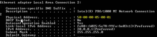
Assign IP addresses to WinServer on its both interfaces
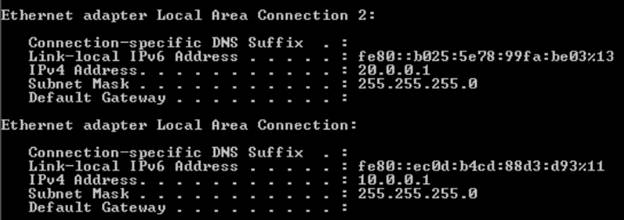
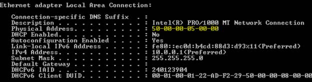
Notice the Mac address of both the interfaces on WinServer interfaces. Marked in yellow.
Notice the Mac addresses on SW interfaces
SW#show interfaces eth0/0 Ethernet0/0 is up, line protocol is up (connected) Hardware is Ethernet, address is aabb.cc00.6000 (bia aabb.cc00.6000) Internet address is 20.0.0.2/24 |
SW#show interfaces eth0/1 Ethernet0/1 is up, line protocol is up (connected) Hardware is Ethernet, address is aabb.cc00.6010 (bia aabb.cc00.6010) Internet address is 10.0.0.2/24 |
The verification of Cisco nexus configure rapid pvst task start by viewing the Root Bridge and Root Port election on a per-switch basis, or by viewing the MAC address table, as the STP topology ultimately controls which interfaces can participate in MAC address learning.
Below we see that for VLAN 10, NXOS01 is elected the Root Bridge. This implies that all of its VLAN 10 links will be Designated ports in the Forwarding state.
NXOS01# show spanning-tree vlan 10 VLAN0010 Spanning tree enabled protocol rstp Root ID Priority 4106 Address 5000.0001.0007 This bridge is the root Hello Time 2 sec Max Age 20 sec Forward Delay 15 sec Bridge ID Priority 4106 (priority 4096 sys-id-ext 10) Address 5000.0001.0007 Hello Time 2 sec Max Age 20 sec Forward Delay 15 sec Interface Role Sts Cost Prio.Nbr Type —————- —- — ——— ——– ——————————– Eth1/1 Desg FWD 20000 128.1 P2p Eth1/2 Desg FWD 20000 128.2 P2p Eth1/3 Desg FWD 99999 128.3 P2p Eth1/4 Desg FWD 99999 128.4 P2p Eth1/5 Desg FWD 20000 128.5 P2p Eth1/6 Desg FWD 20000 128.6 P2p |
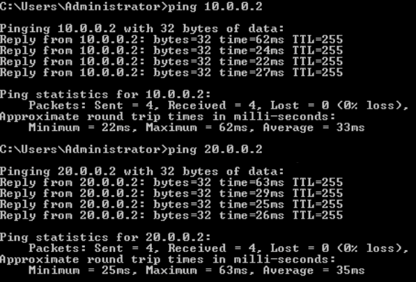
Try to send PING traffic from SW to WinServer or vice versa. In case traffic dies out, use continuous ping to generate traffic.
SW#ping 10.0.0.1 Type escape sequence to abort. Sending 5, 100-byte ICMP Echos to 10.0.0.1, timeout is 2 seconds: .!!!! Success rate is 80 percent (4/5), round-trip min/avg/max = 21/24/31 ms SW#ping 20.0.0.1 Type escape sequence to abort. Sending 5, 100-byte ICMP Echos to 20.0.0.1, timeout is 2 seconds: .!!!! Success rate is 80 percent (4/5), round-trip min/avg/max = 26/30/36 ms |
MAC addresses for VLAN 10 are being learned in ports Eth2/5 and Eth1/1, which implies that NXOS04 and NXOS02 on the other end of these links, respectively, have chosen those ports as their Root Ports.
NXOS01# show system internal l2fwder mac Legend: * – primary entry, G – Gateway MAC, (R) – Routed MAC, O – Overlay MAC age – seconds since last seen,+ – primary entry using vPC Peer-Link, (T) – True, (F) – False, C – ControlPlane MAC VLAN MAC Address Type age Secure NTFY Ports ———+—————–+——–+———+——+—-+—————— * 10 5000.0005.0000 dynamic 00:10:18 F F Eth1/1 * 10 aabb.cc00.6010 dynamic 00:10:22 F F Eth1/5 |
Use command “show mac address-table dynamic vlan 10” on physical switch which represents the same output.
In rapid pvst Cisco configuration on nexus switch output below, NXOS02 choose E1/1 as the Root Port to reach NXOS01. Although all ports have the same cost of 2000, E1/1 has the lowest Port ID (port priority and port number) on the other end of the link.
NXOS02# show spanning-tree vlan 10 VLAN0010 Spanning tree enabled protocol rstp Root ID Priority 4106 Address 5000.0001.0007 Cost 20000 Port 1 (Ethernet1/1) Hello Time 2 sec Max Age 20 sec Forward Delay 15 sec Bridge ID Priority 8202 (priority 8192 sys-id-ext 10) Address 5000.0002.0007 Hello Time 2 sec Max Age 20 sec Forward Delay 15 sec Interface Role Sts Cost Prio.Nbr Type —————- —- — ——— ——– ——————————– Eth1/1 Root FWD 20000 128.1 P2p Eth1/2 Altn BLK 20000 128.2 P2p Eth1/3 Desg FWD 20000 128.3 P2p Eth1/4 Desg FWD 20000 128.4 P2p Eth1/5 Desg FWD 20000 128.5 P2p Eth1/6 Desg FWD 20000 128.6 P2p |
Per the view of the CAM table below, we see that NXOS02 learns MAC addresses for VLAN 10 in Eth1/1, its root port, and Eth2/5, the downstream link connecting to NXOS03. Look on for mac addresses in VLAN 10
NXOS02# show system internal l2fwder mac Legend: * – primary entry, G – Gateway MAC, (R) – Routed MAC, O – Overlay MAC age – seconds since last seen,+ – primary entry using vPC Peer-Link, (T) – True, (F) – False, C – ControlPlane MAC VLAN MAC Address Type age Secure NTFY Ports ———+—————–+——–+———+——+—-+—————— * 10 5000.0005.0000 dynamic 00:17:28 F F Eth1/5 * 10 aabb.cc00.6010 dynamic 00:17:32 F F Eth1/1 |
Use command “show mac address-table dynamic vlan 10” on physical switch which represents the same output.
On the next downstream switch, NXOS03, we see that it has chosen Eth1/8, a link to NXOS02, as its Root Port. This is because other possible paths to the Root Bridge have had their cost raised to 99999.
The end result is that traffic received from Win Server in VLAN 10 going to SW is first forwarded to NXOS02, then to NXOS01, then to NXOS04, and finally to SW.
Note: Use command “show mac address-table dynamic vlan 10” on physical switch which represents the same output.
Likewise, traffic in VLAN 20 from SW can be verified to follow the path of NXOS03 ->NXOS01 ->NXOS02 ->NXOS04 ->Win Serverby the CAM tables below.
Look only for mac addresses in VLAN 20
NXOS03# show system internal l2fwder mac Legend: * – primary entry, G – Gateway MAC, (R) – Routed MAC, O – Overlay MAC age – seconds since last seen,+ – primary entry using vPC Peer-Link, (T) – True, (F) – False, C – ControlPlane MAC VLAN MAC Address Type age Secure NTFY Ports ———+—————–+——–+———+——+—-+—————— * 20 5000.0005.0001 dynamic 00:00:07 F F Eth1/3 * 20 aabb.cc00.6000 dynamic 00:00:07 F F Eth1/8 NXOS01# show system internal l2fwder mac Legend: * – primary entry, G – Gateway MAC, (R) – Routed MAC, O – Overlay MAC age – seconds since last seen,+ – primary entry using vPC Peer-Link, (T) – True, (F) – False, C – ControlPlane MAC VLAN MAC Address Type age Secure NTFY Ports ———+—————–+——–+———+——+—-+—————— * 20 5000.0005.0001 dynamic 00:01:29 F F Eth1/1 * 20 aabb.cc00.6000 dynamic 00:01:29 F F Eth1/3 NXOS02# show system internal l2fwder mac Legend: * – primary entry, G – Gateway MAC, (R) – Routed MAC, O – Overlay MAC age – seconds since last seen,+ – primary entry using vPC Peer-Link, (T) – True, (F) – False, C – ControlPlane MAC VLAN MAC Address Type age Secure NTFY Ports ———+—————–+——–+———+——+—-+—————— * 20 5000.0005.0001 dynamic 00:06:05 F F Eth1/3 * 20 aabb.cc00.6000 dynamic 00:06:05 F F Eth1/1 NXOS04# show system internal l2fw mac Legend: * – primary entry, G – Gateway MAC, (R) – Routed MAC, O – Overlay MAC age – seconds since last seen,+ – primary entry using vPC Peer-Link, (T) – True, (F) – False, C – ControlPlane MAC VLAN MAC Address Type age Secure NTFY Ports ———+—————–+——–+———+——+—-+—————— * 20 5000.0005.0001 dynamic 00:07:44 F F Eth1/7 * 20 aabb.cc00.6000 dynamic 00:07:44 F F Eth1/3 |
In case you want to learn more in-depth on all Cisco nexus technology topics using self paced videos and practice lab.
Learn Nexus with Training Videos & lab. Explanation of each topics using the lab. | 30 Hours Videos and 50 hours of Remote Lab access for a month |
Related Articles:
How to Configure Port Channel on Nexus Switches
Learn About Cisco Nexus 9k Switches Architecture
How to Replace Nexus Switch in VPC
All the very best!
Deepak Sharma, CCIE#37340
Comments (0)

Categories
Popular posts

Cisco Nexus Port Channel: Configuring ...
26 Apr 2024
Configure Rapid PVST on Cisco Nexus
26 Apr 2024
Palo Alto Exam Cost: PCNSA, PCNSE & More
26 Apr 2024
Cisco ACI VPC Configuration Task Steps
6 Jan 2024Recent posts
Network Hardware Devices: Explained
26 Apr 2024
Configure Rapid PVST on Cisco Nexus
26 Apr 2024
Palo Alto Exam Cost: PCNSA, PCNSE & More
26 Apr 2024
Cisco Nexus Port Channel: Configuring ...
26 Apr 2024