Task
● In this task, Configure DHCP Snooping
Configuration
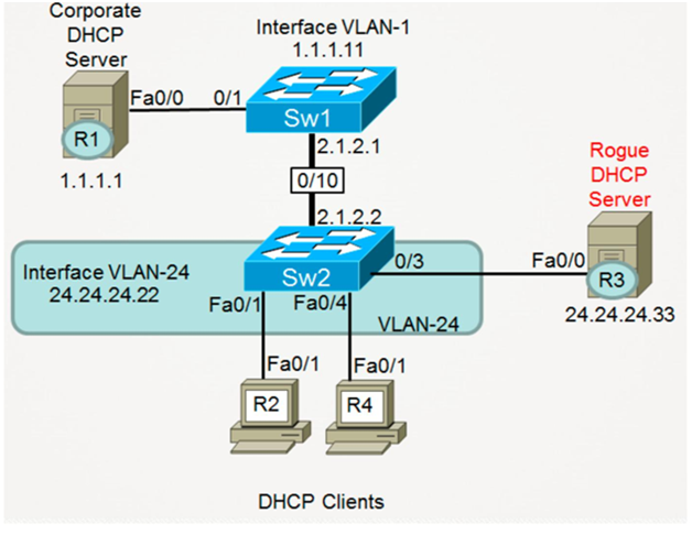
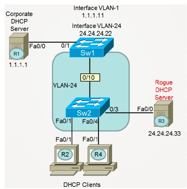
Task 1 : Configure the R1 as DHCP Server and following configuration on R1
R1 : Configure Eth0/0 with IP address 1.1.1.1/24
Configure DHCP pool for Vlan 24 On R1
Configure the Default route from R1 to SW2 Interface Eth10/0 IP address 2.1.2.2
interface Ethernet0/0 ip address 1.1.1.1 255.255.255.0 duplex auto speed auto ip route 0.0.0.0 0.0.0.0 1.1.1.11 ip dhcp pool CCNP network 24.24.24.0 255.255.255.0 default-router 24.24.24.22 lease 7 |
Task 2 : Configure the SW1 With Following Configuration
SW1 : Configure Eth1/0 in vlan 1
Configure L3 vlan 1 on SW1 with Following Information : Ip address 1.1.1.11/24 Configure eth10/0 with ip address 2.1.2.1/24
Configure Default route Pointing to SW2 Interface eth10/0 ip address 2.1.2.2 Shut Down all other Ports on SW1 ( Eth11/0 , eth12/0)
ip routing interface Ethernet1/0 switchport mode access spanning-tree portfast interface Ethernet10/0 no switchport ip address 2.1.2.1 255.255.255.0 ! interface Vlan1 ip address 1.1.1.11 255.255.255.0 no shut ! ip classless ip route 24.24.24.0 255.255.255.0 2.1.2.2 SW1(config)#int eth11/0 SW1(config-if)#shut SW1(config-if)#int eth12/0 SW1(config-if)#shut SW2: Configure the interface Eth2/0 , eth3/0 ,eth4/0 in Vlan 24 Configure L2 vlan 24 Configure int eth10/0 withip address 2.1.2.2 Configure Interface Vlan 24 with Following IP 24.24.24.22/24 Configure Default route Pointing to 2.1.2.1 interface Ethernet10/0 no switchport ip address 2.1.2.2 255.255.255.0 ! interface Ethernet2/0 switchport access vlan 24 switchport mode access spanning-tree portfast ! Interface Ethernet3/0 switchport access vlan 24 switchport mode access spanning-tree portfast ! interface Ethernet4/0 switchport access vlan 24 switchport mode access spanning-tree portfast ! interface Vlan24 ip address 24.24.24.22 255.255.255.0 ip helper-address 1.1.1.1 no shut ! ip route 0.0.0.0 0.0.0.0 2.1.2.1 |
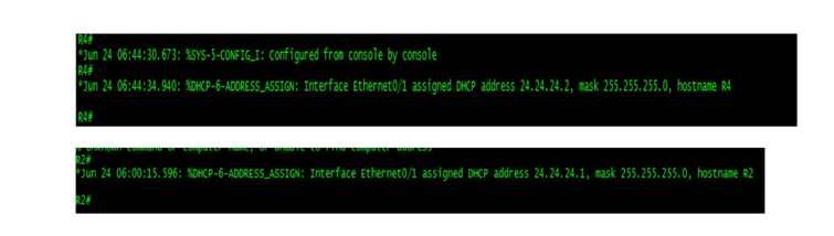
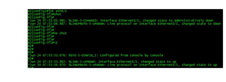
Task 3 : Configure R2 interface eth0/1 so that it can receive the Ip address from DHCP server . Configure R4 interface eth0/1 so that it can receive the Ip address from DHCP server
R2(config)#int eth0/1 R2(config-if)#ip address dhcp R2(config-if)#no shut R4#sh run int eth0/1 interface Ethernet0/1 ip address dhcp end |
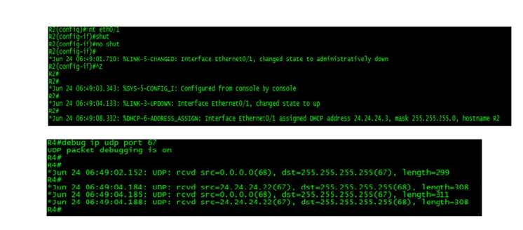
Currently, any broadcasts sent by either Client-R2 or Client-R4 are flooded by Switch-2 and visible to the other clients as well as Router-3 (Rogue DHCP Server). This means that when (as an example) Client-R2 transmits a broadcast DHCP Discover packet, and broadcast DHCP Request packet, these are visible to other devices within VLAN-24. Verify this for yourself by doing the following:
Ensure that you have two Telnet windows open at the same time: a window to R2, and another window to R4.
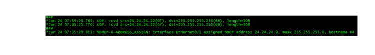
On Client-R4, enter the command debug ip udp port 67. This command will display any IP packets that Client-R4 has received and forwarded to its own CPU, with a source, or destination, UDP port 67 (the DHCP Server port).
On Client-R2, shutdown interface FastEthernet0/1 and then enable this interface. The debug running on Client-R4 will prove that it has received the DHCP broadcasts sent to and from Client-R2.
Turn off all debugging on Client-R4 with the command undebug all (or simply u all).
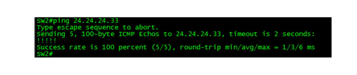
Task 4: Complete the configuration of R3 as a Rogue DHCP Server by doing the following:
Enable the command service dhcp.
Create a DHCP Pool
Your pool should provide IP addresses within the correct subnet of 24.24.24.0/24. Your pool should be configured to intentionally offer an INCORRECT IP address of 24.24.24.33 (the Rogue DHCP Server) as the Default-Router for all DHCP clients.
Your pool should be configured with a DHCP Lease time of 7 days.
R3(config)#int eth0/0 R3(config-if)#ip address 24.24.24.33 255.255.255.0 R3(config-if)#no shut R3(config-if)#exit R3(config)#ip route 0.0.0.0 0.0.0.0 24.24.24.22 service dhcp ip dhcp pool CCNP network 24.24.24.0 /24 default-router 24.24.24.33 lease 7 |
Typically, when DHCP clients receive more than a single offer in response to their DHCP Discover packet, they will accept the very first offer they received.
In this case, because the Rogue DHCP Server is located in the same VLAN as the DHCP clients, any DHCP offer sent from this device should be accepted before any legitimate offer sent from the Corporate DHCP Server. This will result in DHCP clients being given an IP address in the correct subnet, but their default-gateway assignment will be wrong. Any packets they attempt to send off-subnet will be sent to R3 (the Rogue DHCP Server) because the clients believe that device is their Default-Gateway.
To verify this:
Disable interface Ethernet0/1 on Client-R2.
Re-enable this interface.
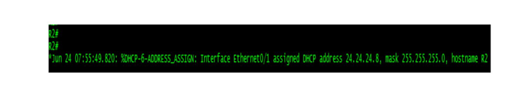
Watch for this interface to be assigned a DHCP Address.
To prove that this address came from the Rogue DHCP Server, issue the command show ip route and notice that you now have a default route to 24.24.24.33. This route SHOULD have pointed to 24.24.24.22 (your DHCP Relay Agent/Default-Gateway).
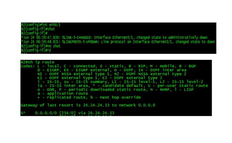
If the above steps do not work, and you still have a default-route pointing at your legitimate Default-Gateway of 24.24.24.22, disable Ethernet0/1 on CLient-R2, wait at least 30 seconds, and then enable this interface again.
Task 5:
Configure DHCP Snooping on Switch-2.
Verify that DHCP Snooping is functional by:
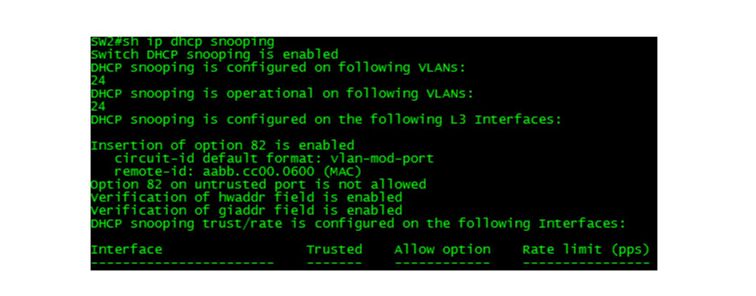
Verify that the DHCP Snooping feature has been enabled correctly by viewing the output of the command show ip dhcp snooping.
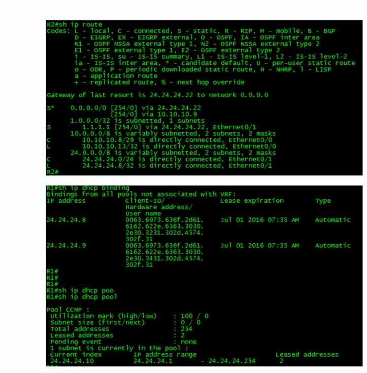
View the DHCP Snooping Binding Database and look for entries created by DHCP Clients R2 and R4.
Verify that all DHCP clients received their DHCP information from the Corporate DHCP Server.
SW2(config)#ip dhcp snooping
SW2(config)#ip dhcp snooping vlan 24
R2(config)#int eth0/1 R2(config-if)#shut R2(config-if)#no shut R4(config)#int eth0/1 R4(config-if)#shut R4(config-if)#no shut |
Task 6:
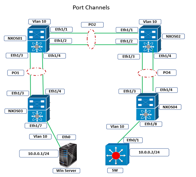
Notice that in the previous steps, you enabled DHCP Snooping on a switch (Switch-2) that was configured as a DHCP Relay Agent. In other words, when Switch-2 receives DHCP broadcasts on its VLAN-24 Switched Virtual Interface, it encapsulates those and routes them toward the Corporate DHCP Server as unicasts.
Now, change the configuration of Switch-1 and Switch-2 so they match the topology diagram below (notice that Switch-1 is now configured as the DHCP Relay Agent, and the link between Switch-1 and Switch-2 is a Layer-2 Access Switchport. Do NOT change any of your existing DHCP Snooping configuration on Switch-2.
SW1(config)#int eth10/0 SW1(config-if)#switchport mode access SW1(config-if)#switchport access vlan 24 interface vlan 24 ip address 24.24.24.22 255.255.255.0 ip helper-address 1.1.1.1 no shut SW2(config)#int eth10/0 SW2(config-if)#switchport SW2(config-if)#switchport access vlan 24 SW2(config)#no int vlan 24 |
Test to see if DHCP Snooping is still functional on Switch-2. If not, do you know WHY?
You should have noticed on both Client-R2 and Client-R4 that they are no longer able to obtain DHCP information from any DHCP Server.
Fix DHCP Snooping on Switch-2 so that both DHCP clients can, once again, obtain DHCP information from the Corporate DHCP Server.
SW2(config)#no ip dhcp snooping information option SW2(config)#int eth10/0 SW2(config-if)#ip dhcp snooping trust SW2(config-if)#^Z |
What did you learn about DHCP Snooping after changing the topology?
When a switch is operating as a Layer-3 switch and a DHCP Relay Agent, the Layer-3 SVI that receives inbound DHCP broadcasts from clients is, by default, trusted by DHCP Snooping. So there is no need to configure any interfaces (physical or virtual) as DHCP Snooping Trusted interfaces.
When a switch is operating as a Layer-2 switch, and all DHCP clients as well as any ports that lead to trusted DHCP servers are Layer-2 Switchports, then the physical interfaces leading upstream to trusted DHCP servers must be configured with the ip dhcp snooping trust command.
When a switch is operating as a Layer-2 switch, it will, by default, insert the DHCP Option-82 into any DHCP client packets it receives. However, most DHCP servers (including Cisco routers and switches configured as DHCP servers) cannot recognize Option-82 and will drop any DHCP client packets that contain this option. To fix this, we needed to configure the DHCP snooping switch to NOT insert Option-82 into DHCP Client packets by using the command no ip dhcp snooping information option.
Comments (0)

Categories
Popular posts

Cisco Nexus Port Channel: Configuring ...
4 Apr 2024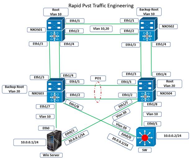
Configure Rapid PVST on Cisco Nexus
5 Apr 2024
Palo Alto Exam Cost: PCNSA, PCNSE & More
28 Mar 2024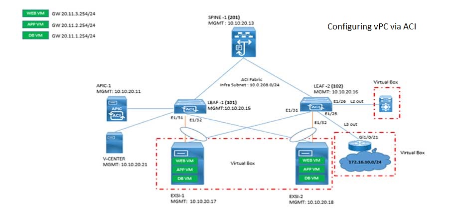
Cisco ACI VPC Configuration Task Steps
6 Jan 2024Recent posts

AWS Certification Path: Amazon Cloud
18 Apr 2024
SD-WAN Vendors Comparison: Choosing the ...
16 Apr 2024
CCNP Certification Cost and Exam Fees
12 Apr 2024
Configure Rapid PVST on Cisco Nexus
5 Apr 2024